Fast Pyrolysis of Low Density Polyethylene and the Upgrading of its Bio-oil into Heating Oil
Background
Low density polyethylene constitutes a significant component of municipal solid waste. Like other types of plastic that find themselves into municipal solid waste stream, it has a high H:C ratio, and a high volatile matter content according to data shown in their elemental and proximate analyses. Low density polyethylene unfortunately also presents a strong environmental challenge because even when dumped into landfills would not be microbially broken down to reduce bulk: instead it is degraded only very slowly with time to generate micro-plastic materials that find themselves in the hydrological cycle as they percolate into ground water aquifer
With the increasing need for alternative energy sources, there is need to thermo-chemically convert the bio-oil produced from the pyrolysis of low density polyethylene into higher calorific value heating oil. The pyrolysis of low density polyethylene for the generation of bio-oil is technically justified by its high H:C ratio versus biogenic biomass feedstock. This means the bio-oil derived from the pyrolysis of low density polyethylene is more likely going to have a greater fraction of aliphatic, cyclic and aromatic hydrocarbons which inherently increases its fuel value.
The fast pyrolysis of low density polyethylene under limited oxygen conditions produces a product that is richer in bio-oil versus syngas and char. Traditional fast pyrolysis methods use thermal cracking at high temperatures to enable the break-down of high molecular weight polymers in the biomass structure – lignin, cellulose and hemicellulose into low molecular weight oxygenated compounds. A reactor temperature ramp rate of about 100-200 oC/s, a solid residence time of 10- 25 minutes and a vapour residence time of 0.5-10 seconds are needed to achieve an average bio oil yield of between 60-75 wt % of the pyrolysis products
To achieve this using an auger pyrolyzer, the biomass feeding rate has to be carefully calibrated against the time the biomass remains in the reactor for conversion into products. An initial reactor heater temperature is set and then the low density polyethylene plastic is introduced from a top hopper when the temperature of the reactor is still below the pyrolysis temperature. A heater ramp (heating) rate is selected (within the range of 100-200 oC/s) and the reactor temperature is increased at that rate until the final pyrolysis temperature is achieved. The time it takes to hit this operational temperature must not exceed the time it takes for complete reaction (residence time). Fast pyrolysis temperatures are typically between 450 and 850 oC, although lower temperatures in this range are preferred to reduce the chance of producing gaseous fractions at higher temperatures. Fast pyrolysis produces bio-oil containing hundreds of oxygenated compounds. Typical organic molecules include: organic acids, alcohols, aldehydes, esters, ketones and guaianols. Most of these oxygenates compounds are hydrocarbon derivatives and burn readily although their high levels of oxygen, nitrogen, sulfur, viscosity and acidity make them not suitable for use as fuels in automobile engines. In particular bio-oil produced through non-catalytic route contains a high amount of long chain waxes that must be further cracked to make the oil have more value. Waxes are more viscous and tend to block pipes and tubes if not immediately cracked to produce lower molecular weight hydrocarbons fractions.
Overcoming the high activation energy barrier faced by the external heating in thermal cracking pyrolysis process is challenge that consequently increases process temperatures. Solid catalysts systematically help reduce the activation lowering process temperatures and improving and upgrading the overall process itself. This means using a catalyst to achieve biomass thermochemical conversion and the possible cracking of the bio-oil fractions into low molecular weight compounds also upgrades the pyrolysis process. The use of catalysts reduces the proportion of wax produced while also increasing the bio-oil yields.
Solid/heterogeneous catalysts in direct feedstock-catalyst contact applications are typically used in plug flow reactors. Typical candidate catalysts are pure zeolites such as ZSM-5, HZSM-5 and reforming catalysts. Reforming catalysts are bi-functional and have both active metal and acid sites. Some acid sites of pure zeolite catalysts are doped with transition metals such as Co, Ni, Pt, Mo via wet impregnation (sol gel) techniques thereby conferring both native acidic and metal catalytic activities. This is the bi-functional capability that pure zeolites don’t have. Active metal sites catalyze hydrogenation and dehydrogenation and the product olefins move to the acid sites where they undergo oligomerization, isomerization, cyclization and aromatization followed by the hydrogen transfer reaction. These interdependent reactions create more branched hydrocarbons, more aromatics and a bio-oil that has more fuel value than you would get from conventional thermal cracking processes or even from the use of pure zeolite catalysts. However, steps have to be put in place to recover catalyst and to regenerate and reuse to reduce cost and maintain efficiency. Generally, reforming catalysts show a higher conversion, higher bio-oil yield and carbon efficiency for plastic in general when the primary objective is the production of bio-oil.
A delicate balance has to be struck between the use of microporous and mesoporous catalysts to reduce surface coke formation. This balance also allows proper mass transfer of cracked products through pore sizes into the deeper catalyst framework for more secondary cracking to occur. When this happens the higher fuel quality of the bio-oil reduces downstream upgrading steps. The catalyst crystallinity, acidity, BET surface area are important parameters for activity, product selectivity, stability and the cracking of long chain molecules. Whether thermal or catalytic pyrolysis is used or not the fact remains that the bio-oil that is produced remains crude and needs upgrading as the following property table shows.

In particular, its water content must be reduced to less than 5 % while simultaneously reducing viscosity. While this will not take other parameter values close enough to their ASTM specifications for diesel the oil’s heating value will increase making the upgraded product useful at a minimum in heating applications.
Pyrolysis
When catalytic cracking is used to produce bio-oil, the low density polyethylene is crushed and mixed with the solid catalyst. For a simple hopper pyrolyzer, the mixture is then introduced into a hopper and is sent into the reaction zone of the reactor by means of a rotating auger. Once in the reaction zone the ramp rate of the heater is applied and the feedstock is pyrolyzed at the final temperature. The vapour of pyrolysis is run through a condenser or through multiple condensers to condense the bio-oil while the syngas exits. Due to its density, char falls off at the end of the reactor and is collected. The collected bio-oil undergoes further processing involving several water removal steps to include among others sedimentation and decantation, spinning under high rpm with a centrifuge etc. A schematic of a simple auger-hopper pyrolyzer is shown below. It could be used in applications where bio-oil production is central with a separate upgrading setup. Its construction is simple and more economical especially when the goal is to produce bio-oil for heating purposes.

Simple auger pyrolyzer for bio-oil production: auger is within a tubular reactor that is heated by a heater with selectable ramp rates; feedstock will be at exit of tube when final heating temperature of reaction has been attained for fast pyrolysis
Upgrading oil for Heating Application
The bio-oil produced from the process of pyrolysis whether via thermal or catalytic cracking needs to be processed or upgraded to obtain a product that can be used in modified engines, generators and turbines or burned to produce heat for residential homes and in industrial applications. Upgrading methods include extraction, solvent addition, emulsification, esterification/alcoholysis, use of supercritical fluids, catalytic hydrotreating, catalytic cracking, steam reforming, filtration, distillation, neutralization etc. Each of these methods has its inherent pros and cons, but results in an improved bio-oil at the end of the treatment method. The method selected depends on the quality of bio-oil needed, its final use and the feedstock used. The end result is to refine the oil to get a product amenable to cited applications or which can be blended with diesel to be combusted in the hybrid engines of large trucks and trailers.
For a bio-oil that is upgraded to a product that is useful for domestic heating, solvent extraction is selected because, it is simple, operates under mild conditions and uses chemical solvents that are readily available. The main drawback is that there is no chemical reaction to convert undesired chemicals in some fractions of the finished products. The sequence of raw bio-oil grading suggested includes:
i) Bio-oil dewatering via centrifugation followed by decanting;
ii) Fractionation and distillation of dewatered oil;
iii) Sequential vapour condensation and liquid withdrawal;
iv) Solvent treatment of the various condensation fractions;
v) Characterization of the various fractions and product grading.
Centrifugation and water removal
The bio-oil that would have condensed from the pyrolysis vapour is centrifuged under very high RPMs. All the organic components, that make up the bio-oil are separated from the denser aqueous phase. A good separation leaves the organic bio-oil fraction at the top while the water (aqueous phase) settles at the bottom.
Fractionation/distillation of dewatered bio-oil and sequential condensation of vapour
The dewatered bio-oil is heated in a batch mode in a vertical stainless steel column at a temperature between 200-300oC. The vapour leaves at the top of the column and is condensed in an overhead condenser whose temperature is set at between 100-170 oC. The first cut of the bio-oil will be compounds with condensation temperatures in this range to include: sugars, lignin, oligomers and some phenols. When there is no change in the mass of collected liquid, the fractionation at this temperature is discontinued. Hence is advisable to place condenser on a scale balance to read bio oil mass in real time. The liquid is collected and treated with specified solvents that might include ethyl acetate, acetone, methanol and ethanol. The bio-oil/solvent mass ratio is varied to get good HHV, viscosity and other desired fuel properties. Applicable condensers include: (i) air-coolers in which the temperature of the condenser can be quickly reduced by increasing air flow rates, (ii) compact condensers that come with refrigerants with set condensation temperatures.
The fractionation and distillation temperature of the residual bio-oil in the column is kept constant after the first liquid fraction is removed from the condenser. However, the condenser temperature is lowered to 50 and 90 oC. More volatile fractions are condensed and include: water, lighter organic acids and other volatiles. The condensation temperature is further lowered to between 25 and 80 oC to condense more light fractions including water. These two cuts that have water might need to undergo further centrifugation to separate the water from the organic phase and improve the fuel value.
Hence three or more fractions from the bio-oil might be obtained. These individual fractions are characterized using appropriate ASTM methods and graded based on quality and fuel values.
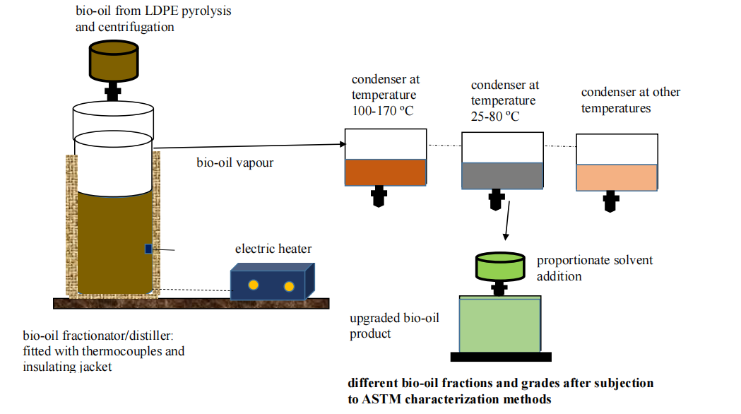
Bio-oil upgrading steps: fractionation, sequential vapour condensation, solvent addition and ASTM characterization and grading
Author: Eliasu A Teiseh
R&D Head